
Topographic Surveys are used to identify and map the contours of the ground and existing features on the surface of the earth or slightly above or below the earth’s surface (i.e. trees, buildings, streets, walkways,
manholes, utility poles, retaining walls, etc.). If the purpose of the survey is to serve as a base map for the design of a residence or building of some type, or design a road or driveway, it may be necessary to
show perimeter boundary lines and the lines of easements on or crossing the property being surveyed, in order for a designer to accurately show zoning and other agency required setbacks.
Topographic surveys, may be required as part of real estate transactions, civil engineering design and construction projects, including:
Road or bridge design or improvements.
Grading or drainage
projects.
New construction.
Remodeling projects to existing structures.
Utility design.
Topographical land surveys or geomatics, as it is becoming known, are carried out with the use of the latest
Leica Instrumentation linked to full keyboard data logging equipment for fast and accurate data collection. All of our instruments have the facility of remote surveying with the use of those hard to reach places.
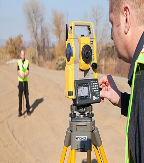
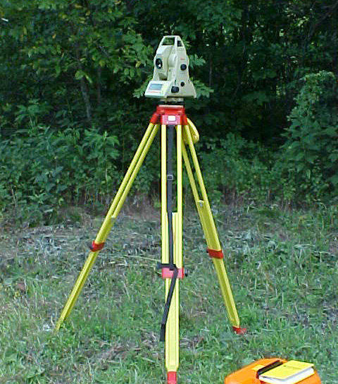
Total station is a surveying equipment combination of Electromagnetic Distance Measuring Instrument and electronic theodolite. It is also integrated with microprocessor, electronic data collector and storage system. The instrument can be used to measure horizontal and vertical angles as well as sloping distance of object to the instrument.
The technique widely known as land surveying has been in use for centuries and is known as the second oldest profession humanity has ever conceived. Because humans always had the need to know exactly where they were located and accurately determine their position in the planet, surveying was created back in ancient Egypt with the use of rope extensions and the applications of uncompounded geometry. Since those times, many things have evolved making tools and other accessories easier to use and to find accurate data, specially in the always important field of land surveying.
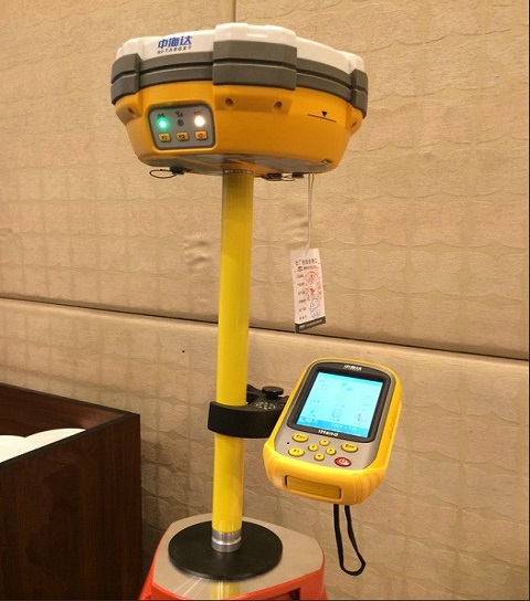

The DGPS (Differential Geographic Positioning System) Survey:
These are surveys which are carried out using the differential GPS. It achieves higher positional accuracy by making use of the differential
capabilities of two GPS antenna linked by a radio signal.
The DGPS Survey main features are:
Position is determined by distance from at least 4 satellites
Time taken by signal to travel from satellite to antenna used to determine the distance.
The
base station calculates the difference between the specified coordinates of its location and those indicated by the satellites.
The base is continuously broadcasting a signal to the rover of this difference.
The rover then uses this same difference to accurately determine it’s location.
Hydrological surveys involving the mapping of drainage channels, fleets, reens and other water courses to allow the preparation of flood risk assessments for ecological planning gain and the creation of wetland
nature reserves. Survey works can include flow data and water quality sampling, analysis and interpretation.
Water quality surveys are carried out to determine the chemical and ecological quality of surface
water to assess historic and current impact from industrial and agricultural sites. Recommendations can then be provided to improve or manage water quality to remove third party risks and particularly to remove
the potential for Part IIA notification.
Hydrogeological Surveys are carried out to determine groundwater levels, chemical quality and hydraulic characteristics. Groundwater modelling packages can then be
prepared using P20, Consim and degradation modelling, to allow comprehensive environmental risk modelling.
Generally, unless specified undisturbed soil samples (UDS) was obtained at every 3.0 m interval starting from 1.0 m in all type of soil along the bore depth upto SPT ‘N’ Values of less than 50. Sampler was 75 mm / 100 mm internal diameter and generally 450 mm long. Thin walled open drive sampler was used in cohesive strata.
The preliminary survey is a relatively large scale instrument survey conducted for the purpose of collecting all the physical information which affects the proposed location of a new highway or improvements to an existing highway. In the case of new roads, it consists of running an accurate traverse line along the route previously selected on the basis of the reconnaissance survey. In the case of existing roads where only improvements are proposed, the survey line is run along the existing alignment. During this phase of the survey, topographic features and other features, like, houses, monuments, places of worship, cremation or burial grounds, utility lines, existing road and railway lines, stream, river, canal crossings, cross-drainage structures, etc. are tied to the traverse line. Longitudinal-sections and cross sections, are taken and bench marks established. The data collected at this stage will form the basis for the determination of the final center line of the road. For this reason, it is essential that every precaution should be taken to maintain a high degree of accuracy.
Besides the above, genial information which maybe useful in fixing design features within close limits is collected during this phase. The information may concern traffic, soil, construction materials, drainage, etc. and may be collected from existing records as through intelligent inspection/simple measurements. Detailed investigations dealt with in section 10 through 16 are not envisaged at this stage. It may be found convenient to divide the road into homogeneous sections from traffic consideration and prepare a typical estimate for one km stretch as representative of each homogeneous section. With the data collected, it should be possible to prepare rough cost estimates within reasonably close limits for obtaining administrative approval, if not already accorded and for planning further detailed survey and investigations. particular, information may be collected regarding :-
(i) The highest sub-soil and flood water levels, the variation between the maximum^ and minimum, and the nature and extent of inundation, if any, gathered from local enquires or other records. These should be correlated to data about the maximum and minimum
rainfall and its duration and spacing, etc. by appropriate hydrological analysis.
(ii) The character of embankment foundations including the presence of any unstable
strata likes micaceous schists, poor drainage or marshy areas; etc. This is particularly necessary in areas having deep cuts to achieve the grade.
(iii) Any particular construction problem of the area,
like, subterranean flow, high level water storage resulting in steep hydraulic gradient across the alignment canal crossings- and their closure periods. Information regarding earlier failure? in the area of slides
or settlements of slopes, embankments and foundation, together with causes thereto may also be gathered from records and enquiry where feasible.
(iv) In cut sections, the nature of rock i.e., hard, soft
etc. should be determined by trial pits or boreholes. This is essential to make realistic cost estimates.
1. The preliminary survey starts with running of a traverse along the selected route, adhering as far as possible to the probable final center line of the road. In difficult situations, a secondary traverse
connected to the primary one at either end may also be run. In hilly areas, a trace cut 1.0 to 1 .2 m wide, if required may be made during the preliminary survey. For details in this regard, reference maybe made
to IRC:52 'Recommendations About the Alignment Survey and Geometric Design of Hill Roads".
2. The traverse consists of a series of straight lines with their lengths and intermediate angles measured very carefully. In difficult terrain, the alignment may have to be negotiated through a series of
short chords, preferably, done with a theodolite with Electronic Distance Measurement (EDM) and all angles measured with double reversal method. Global Positioning System (GPS) is also very useful and appropriate
for preliminary survey. The GPS will give locations in co-ordinates all the necessary points on the traverse. GPS is very fast reasonably accurate for preliminary system and computer friendly for data transfer.
Control pillars in cement concrete should be fixed at suitable interval (ranging from 500 m to 2 kms) to have control on accuracy. It also helps in repeating the survey, if required, within the control pillars.
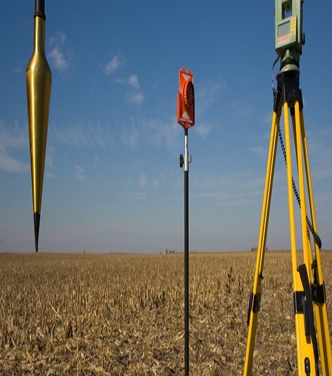
3. Distances along the traverse line should be measured with EDM or total station An accuracy of at least 1 in 10000 should be aimed at mall distance measurement.
4. No hard and fast rule can be laid down as regards distance between two consecutive transit stations^ In practice, the interval will be dictated by directional changes in the alignment, terrain conditions
and visibility. The transit stations should be marked by means of stakes and numbered in sequence. These should be protected and preserved till the final location survey.
5. Physical features, such as, buildings, monuments, burial grounds, cremation grounds, places of worship, posts, pipelines, existing roads and railway lines, stream/'river/canal crossings, cross-drainage
structures, etc. that are likely to affect the project proposals should be located by means of offsets measured from the traverse line. Where the survey is for improving or upgrading an existing road, measurements
should also be made for existing carriageway, roadway and location and radii of horizontal curves. In case of highways in rolling and hilly terrain the nature and extent of grades, ridges and valleys and vertical
curves should necessarily be covered. The width of land to be surveyed will depend on the category of road, purpose of the project, terrain and other related factors. Generally, the survey should cover the entire
right-of-way of the road, with adequate allowance for possible shifting of the center line from the traverse line.
6. Leveling work during a preliminary survey is usually kept to the minimum. Generally, fly levels are taken along the traverse line at 50 meter intervals and at all intermediate breaks in ground. To draw
contours of the strip of land surveyed, cross-sections should be, taken at suitable intervals, generally 100 to 250 m in plain terrain, upto 50 m in rolling terrain, and upto 20 m in hilly terrain. To facilitate
the leveling work, bench marks, either temporary or permanent, should be established at intervals of 250 to 500 meters. The levels should be connected to GTS datum.
7. Field notes of the survey should be clear and concise, yet comprehensive enough for easy and accurate plotting.
8. Apart from traverse survey, general information about traffic, soil, drainage should be collected while the traverse is being run, as mentioned in para 2.
1. Plans and longitudinal sections (tied to an accurate base line) prepared as a sequel to the preliminary survey are referred to for detailed study to determine the final center line of the road. At critical locations, like, sharp curves, hair-pin bends,
bridge crossings, etc., the plan should also show contours at 1-3 meter intervals, particularly for roads in rolling or hilly terrain so as to facilitate the final decision.
2. Scales for the maps should generally be the same as adopted for the final drawings. The following scales are suggested:
(i) Built-up areas and stretches in hilly terrain- 1 : 1,000 for horizontal
scale and 1 : 100 for vertical scale.
(ii) Plain and rolling terrain- 1 : 2,500 for horizontal scale and 1:250 for vertical scale.
3. For study of difficult locations, such as, steep terrain, hair-pin bends, sharp curves, bridge crossings,
etc. it may be convenient to have plans to a larger scale than recommended above. If necessary these plans may show contours preferably at 2 m interval, though this could be varied to 1.5 m according to site condition.
SPT was generally be conducted in boreholes at interval of 1.5 m. The tests were conducted as per IS-2131. For conducting the test, the bottom of the borehole was properly cleaned and split spoon sampler was properly
seated in position in the borehole.
The test is basically a penetration test in which, a thick wall split tube sampler, shall be driven into the undisturbed soil at the bottom of the hole under the blows of
a 63.5 kg drive weight with 75 cm free fall. The sampler shall be first driven through 15 cm as a seating drive. It shall be further driven through 30 cm in two stages of 15 cm each or until 100 blows have been
applied. The number of blows required to drive the sampler in second and third stage for penetration of 15 cm each (total 30 cm) beyond the seating drive shall be termed as “Penetration resistance N”. The samples
collected shall be used as disturbed soil samples for laboratory testing. The split spoon sampler shall conform to IS 9640-1980.
In case the blow count of SPT in soil (including the number of blows for seating)
exceeds 100, the corresponding penetration was recorded and this particular test at that depth stopped.
The sequence of operation for the field investigation was as under:
a. The location of borehole / trial pit was identified on ground with respect to existing structure, change or coordinates.
b. Drilling, sampling and field testing was carried out as per the guidelines given in following paras.
c. The findings of investigation, including field tests, sampling, visual description of strata encountered etc., were recorded in field borehole log.
d. The SPT samples packed in polythene bags and rock cores, duly labeled were preserved in wooden core boxes.
e. The UDS samples were sealed, labeled and preserved as per guidelines given in following paras.
f. Boreholes were terminated as per specifications.
g. Photographic evidence of machine positioned at particular location shall be collected.
h. Ground water table was recorded in each borehole after 24 hrs after completion of borehole.
i. Selected samples were carefully packed and shipped to laboratory for testing.
Boreholes of 150-mm diameter were drilled in soil. Boring was done by rotary Drilling Method and as per the procedure outlined in IS:1892-1979. Boreholes were supported using temporary casing wherever required.
SPT was generally be conducted in boreholes at interval of 1.5 m. The tests were conducted as per IS-2131. For conducting the test, the bottom of the borehole was properly cleaned and split spoon sampler was
properly seated in position in the borehole.
The test is basically a penetration test in which, a thick wall split tube sampler, shall be driven into the undisturbed soil at the bottom of the hole under
the blows of a 63.5 kg drive weight with 75 cm free fall. The sampler shall be first driven through 15 cm as a seating drive. It shall be further driven through 30 cm in two stages of 15 cm each or until
100 blows have been applied. The number of blows required to drive the sampler in second and third stage for penetration of 15 cm each (total 30 cm) beyond the seating drive shall be termed as “Penetration
resistance N”. The samples collected shall be used as disturbed soil samples for laboratory testing. The split spoon sampler shall conform to IS 9640-1980.
In case the blow count of SPT in soil (including
the number of blows for seating) exceeds 100, the corresponding penetration was recorded and this particular test at that depth stopped.
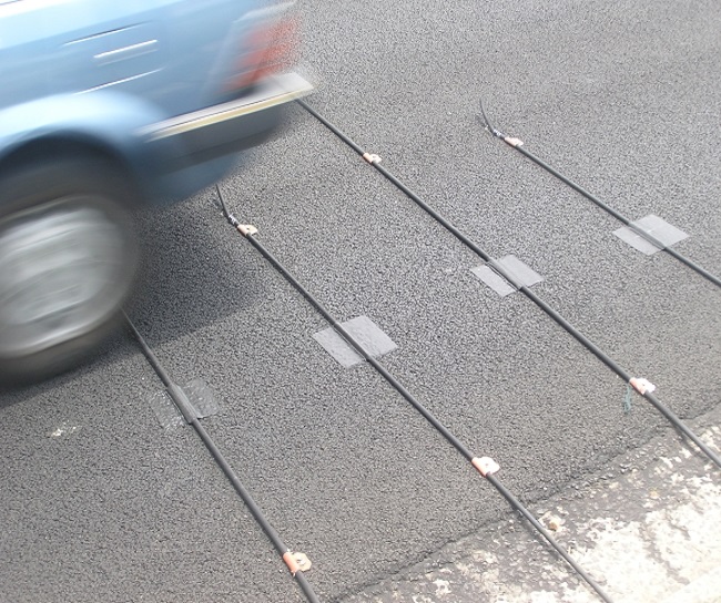
TMC’s are generally used to determine whether the intersection needs a traffic light. Equations are used to decide whether the volume of the traffic determines that a light is needed. This equation is based
on the road classification, entering speed and pedestrian/bicyclist movement through the intersection. This means that TMC’s are the only present option for quantifying traffic flows. This type of survey
are used where the vehicles flow from 3 or more origins and there relative destinations. We can undertake all types of Turning Counts. Sometimes these analyses may have to use different set up of videos
to increase the accuracy of the count. Data can recorded in quarterly or hourly periods. The time periods and Vehicle Classifications can vary depending upon the requirement of client’s.
These surveys
sometimes need a different type of analysis which is known as “Tracking of Vehicles” which have Mentioned in Detail in our Tracking Page.

A Traffic surveying consultancy service is used for making essential measurements to determine the relative position of points and/or physical and cultural details above, on, or beneath the surface of the Earth. These depict the points in a usable form, or to establish the position of points and/or details. Our topographic surveying professionals have the capability of handling combinations of topographic maps, which enable them to come up with accurate results.
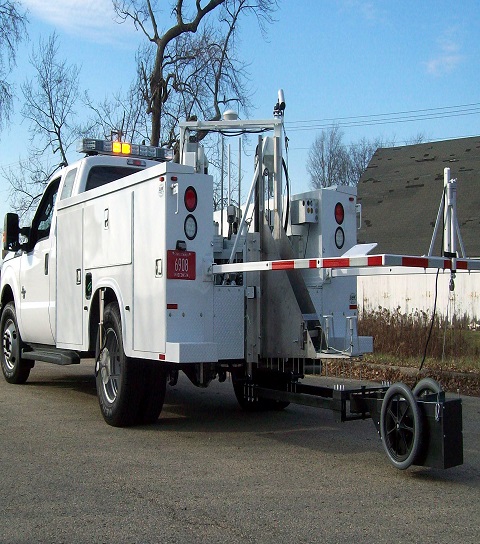
A falling weight deflectometer (FWD) is a testing device used by civil engineers to evaluate the physical properties of pavement. FWD data is primarily used to estimate pavement structural capacity for 1) overlay design and 2) to determine if a pavement is being overloaded. Use includes (but is not limited to) highways, local roads, airport pavements, harbor areas and railway tracks. The machine is usually contained within a trailer that can be towed to a location by another vehicle. It can also be built on a pickup truck or inside a mini van. There are also comprehensive units where a FWD device is mounted on a heavy truck together with a GPR cart and a TMA protection to have a complete road survey vehicle.
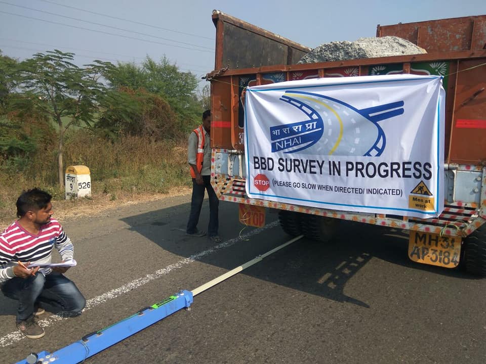
A brief note on BBD Survey : BBD and Bump Integrator This method of test covers a procedure for determination rebound deflection of pavement under static load on the rear axle of the standard truck. The dual wheels of the truck are centred about the point to be tested. The probe is then inserted between the duals and places on the point. The dial gauge is set 1cm and the initial reading is recorded when the deformation is equal to or less than 0.025mm per minute. The truck is then slowly driven for a distance of 270cm and then stopped. The intermediate reading is recorded when the rate of the recovery of the pavement is equal to or less than 0.025mm per minute. Then the truck is further moved forward to 9m. The final reading is recorded when the recovery rate of the pavement is equal to or less than 0.025mm per minute. During the survey the pavement and atmospheric temperatures are recorded at frequent intervals. Soil samples are also collected and tested in the lab for moisture content and plasticity Index. All these data are then processed to get the characteristic deflections. IRC-81 is extensively used to determine the calculation parameters. Corrections for moisture and temperature are applied to get the final results. These results further guide in the design of the overlay thickness.
© 2019 Narendra Geotechnical. All rights reserved
Our services are extremely applauded in the market due to timely completion and consistency. These services are rendered employing the advanced techniques. Owing to high demand, we render our services at nominal costs.