
The sequence of operation for the field investigation was as under:
a. The location of borehole / trial pit was identified on ground with respect to existing structure, chainage or coordinates.
b. Drilling, sampling and field testing was carried out as per the guidelines given in following paras.
c. The findings of investigation, including field tests, sampling, visual description of strata encountered etc., were recorded in field borehole log.
d. The SPT samples packed in polythene bags and rock cores, duly labeled were preserved in wooden core boxes.
e. The UDS samples were sealed, labeled and preserved as per guidelines given in following paras.
f. Boreholes were terminated as per specifications.
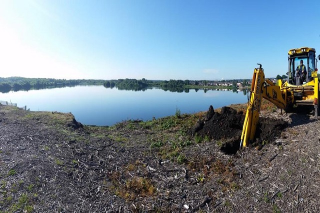
g. Photographic evidence of machine positioned at particular location shall be collected.
h. Ground water table was recorded in each borehole after 24 hrs after completion of borehole.
i. Selected samples were carefully packed and shipped to laboratory for testing.
Boreholes of 150-mm diameter were drilled in soil. Boring was done by rotary Drilling Method and as per the procedure outlined in IS:1892-1979. Boreholes were supported using temporary casing wherever required.
Generally, unless specified undisturbed soil samples (UDS) was obtained at every 3.0 m interval starting from 1.0 m in all type of soil along the bore depth upto SPT ‘N’ Values of less than 50. Sampler was 75 mm / 100 mm internal diameter and generally 450 mm long. Thin walled open drive sampler was used in cohesive strata.
In all boreholes, if undisturbed samples could not be collected due to reasons stated above or if having non-plastic (cohesionless) soil which could not be extracted undisturbed, disturbed soil samples shall be taken at every 1.5 m interval and at significant change of stratum. Soil from split spoon sampler used for standard penetration tests were taken as disturbed samples. These samples were placed without delay in polyethylene bags adequately sealed.
Drilling in rock stratum was carried out using Nx size Bit and Double Tube core barrel. Core drilling was normally carried out with bits which were suitable for the percentage core recovery and diameter required.
Rotary core drilling produced circular cores of a minimum 54 mm diameter throughout the core length. The type and state of the drill bit, feed rates and management of the drill was such that at least 95% core
recovery in any single run can be obtained. Drill runs were normally exceed 1.5m in length unless 100% recovery is being obtained and the core barrel was removed from the drill holes as often as may be required
in order to get the best possible core recovery. Rock cores recovered during drilling were arranged sequentially in core boxes and duly identified. Their Core Recovery (CR) and Rock Quality Designation (RQD) were
recorded in the borelogs. The rock type was identified and the description was presented in the borelogs.
The samples recovered during each run were arranged sequentially in wooden core boxes and the identifications
– Borehole number and piece number was painted on them. Photographs for the rock core samples collected in wooden boxes shall be taken and submitted along with the Geotechnical Interpretative Reports.
Ground water level is recorded in each borehole after 24 hrs and depths are recorded on the Bore logs.
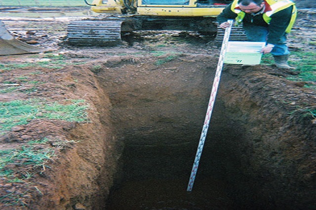
The plan dimensions of the trial pit were 1 m x 1 m and excavated upto 3.00 m depth below proposed ground level (BPGL) unless the hard / competent strata is observed at shallow depth. The ‘log’ of the trial pit is recorded and presented as “Trial Pit Log”.

| Sr No | Code | Specification |
|---|---|---|
| 1 | IS 460-1985 | Specification of test Sieves (All Parts) |
| 2 | IS 1080-1985 | Code of practice for Design and Construction of Shallow Foundations in Soils (Other than Raft, Ring and Shell) |
| 3 | IS 1498-1970 | Indian Standard for Classification and Identification of Soils for General Engineering Purposes |
| 4 | IS 1607-1977 | Methods for test sieving |
| 5 | IS 1888-1982 | Method of load test on soils |
| 6 | IS 1892-1979 | Indian Standard Code of Practice for Subsurface Investigation for Foundations |
| 7 | IS 1904-1986 | Indian Standard Code of Practice for Design and Construction of Foundations in Soils : General Requirements |
| 8 | IS 2131-1981 | Indian Standard Code for Method for Standard Penetration Test for Soils |
| 9 | IS 2132-1986 | Indian Standard Code of Practice for Thin-Walled Tube Sampling of Soils |
| 10 | IS 2720 | Methods for Tests on Soils (All Parts) |
| 11 | IS 2809-1972 | Glossary of terms and symbols relating to soil |
| 12 | IS 2810-1979 | Glossary of terms relating to soil dynamics |
| 13 | IS 2911-2010 | Code of Practice for design and construction of Pile Foundations(All Parts) |
| 14 | IS 2950-1981 | Code of practice for design and construction of raft foundations |
| 15 | IS 4078-1980 | Code of practice for indexing & storage of drill cores |
| 16 | IS 4434-1978 | Code of practice for in-situ vane shear test for soils |
| 17 | IS 4968-1976 | Method of subsurface sounding for soils (All Parts i.e. from 1to 3) |
| 18 | IS 5249-1969 | Method of test for determination of in-situ dynamic properties of soils |
| 19 | IS 5421-2013 | Glossary of terms relating to test sieves and tests sieving |
| 20 | IS 6403-1981 | Code of Practice for determination of bearing capacity of shallow foundations |
| 21 | IS 8009-1976 | Code of practice for calculation of settlement of foundations (AllParts) i.e for Shallow & Deep subjected to symmetrical static vertical loading |
| 22 | IS 9143-1979 | Methods for the determination of Unconfined Compressive Strength of Rock material |
| 23 | IS 9179-1979 | Methods for the determination of Unconfined Compressive Strength of Rock material |
| 24 | IS 9221-1979 | Methods for the determination of Modulus of elasticity and Poisson’s ratio of rock material in uni-axial compression |
| 25 | IS 9640-1980 | Split Spoon Sampler |
| 26 | IS 10074-1982 | Specification for compaction mould assembly for light & heavy compaction test of soils |
| 27 | IS 10077-1982 | Specification for equipment for determination of shrinkage factors |
| 28 | IS 10379-1982 | Code of practice for field control of moisture and compaction of soils for embankment and subgrade |
| 29 | IS 10782-1983 | Method for laboratory determination of dynamic modulus of rock core specimens |
| 30 | IS 10837-1984 | Specification for moulds and accessories for determination of density index of cohesionless soils |
| 31 | IS 11196-1985 | Specification for equipment for determination of liquid limit of soils- cone penetration method |
| 32 | IS 11209-1985 | Specification for Shear box for testing of soils |
| 33 | IS 11229-1985 | Specification of mould assembly for determination of permeability of soils |
| 34 | IS 11315-1987 | Method for the qualitative description of discontinuities in rock mass (All Parts) |
| 35 | IS 11594-1985 | Mild Steel thin walled sampling tubes and sampler heads |
| 36 | IS 13030-1991 | Method of test for laboratory determination of water-content, porosity, density and related properties of rock material |
| 37 | IS 13063-1991 | Code of practice for structural safety of buildings on shallow foundations on rocks |
| 38 | IS:13365-2010 | Quantitative Classification system of rock mass-guidelines (All Parts) |
| 39 | IS 14593-1998 | Design & Construction of bored cast-in-situ piles |
| 40 | founded on rocks MORTH | Specifications for Road & Bridge Work issued by Ministry of Road |
| 41 | IRC 5-1998 | Standard Specifications and code of Practice for Road Bridges |
| 42 | IRC 75-2015 | Guidelines for design of high embankment |
| 43 | IRC 78-2014 | Standard Specification and Code of Practice for Road Bridges |
© 2019 Narendra Geotechnical. All rights reserved
Our services are extremely applauded in the market due to timely completion and consistency. These services are rendered employing the advanced techniques. Owing to high demand, we render our services at nominal costs.